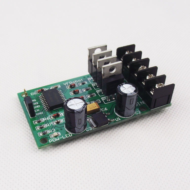
Cheap H Bridge Driver

If you want to buy cheap h bridge motor driver, choose h bridge motor driver from banggood.com. It endeavors to provide the products that you want, offering the best. If you want to buy cheap h bridge, choose h bridge from banggood.com. It endeavors to provide the products that you want, offering the best bang for your buck. Great but Cheap H Bridge Driver, Cheap Electronic Components & Supplies,Integrated Circuits,Home Improvement,Motor Driver, as well as Cheap and more! Online Get Best. Introduction: Simple, Cheap Motor Driver Board for Arduino. Many projects with Arduino often need motors. So, you can use an H-bridge circuit to operate the motors.
William, You can't build an H-bridge from a ULN2003, since it's current-sinking only. An H-bridge consists of two current-sinking and two current-sourcing drivers. If you're designing for mass production, the cheapest way to go is probably discrete transistors: 2 PNPs and 2 NPNs (or their MOSFET equivalents) with associated resistors and diodes. Zetex makes some that might make nice building blocks. Andrea Falconieri S Mp3. The web should be replete with candidate circuits. You will want to design in some current limiting as a protection against short circuits, as well as protection against cross-conduction, which will fry an H-bridge. The Tilden H-bridge with 2n2222 and 2n2907 transistors is a pretty good option.
The cost is 6 transistors and two resistors. The web site has instructions on how to 'free form' the wiring so you don't need any printed circuit board. This is not the cleanest or most efficent design and if you want to have better power usage, you have to add a few more resistors and a couple of diodes. If you have space on a board [noparse][[/noparse]like the SX-28 Proto board or the Propeller Proto board], you can mount your compontents with your processor. ▔▔▔▔▔▔▔▔▔▔▔▔▔▔▔▔▔▔▔▔▔▔▔▔ It's sunny and warm here.
It is always sunny and warm here. (unless a typhoon blows through). Tropically, G. H.264 Dvr Activex Control here. Herzog [noparse][[/noparse] 黃鶴 ] in Taiwan Post Edited (Kramer): 8/21/2008 8:34:49 AM GMT.
The H-Bridge is a circuit which can drive a DC motor in forward and reverse. The motor direction is changed by switching the polarity of the voltage in order to turn the motor one way or the other.
This is easily demonstrated by applying a 9-volt battery to the leads of a small motor and then switching the terminals to change directions. Adobe Acrobat 9.0 Image Conversion Plug-in. The H-Bridge is given it's name based on the basic circuit which demonstrates it's operation. The circuit consists of four switches which complete the circuit when applied in pairs. When switches S1 and S4 are closed the motor gets power and spins. When S2 and S3 are closed the motor gets power and spins in the other direction. Note that S1 and S2 or S3 and S4 should never be closed together in order to avoid a short circuit. Obviously physical switches are impractical since no one is going sit there flipping switches in pairs to get their robot to move forward or in reverse.
That's where the transistors comes in. A transistor acts as a solid state switch that closes when a small current is applied to it's base. Because only a small current is required to activate a transistor we are able to complete one half of the circuit with a single signal. That's enough theory to get started so let's start building. The next step is to set up the transistors. Recall in the theory section that we need four switches to build an H-Bridge, so we'll be using all four transistors here. We're also limited to the layout of a breadboard so the actual circuit will not resemble the letter H.

Let's take a quick look at a transistor to understand the current flow. There are three legs on each transistor known as the collector, base, and emitter.
Not all transistors share the same order so be sure to consult a datasheet if you're not using one of the part numbers mentioned in step one. When a small current is applied to the base, another larger current is allowed to flow from collector to emitter. That's important so I'll say it again. A transistor allows a small current to control a larger current. In this case the emitter should always be connected to ground.
Note that the current flow is represented by a small arrow in the figure below. Now we're going to line up the transistors on the bottom half of the breadboard, flipping the orientation for every other transistor. Each pair of adjacent transistors will serve as one half of the H-Bridge. An adequate space needs to be left in the middle in order to fit some jumpers and eventually the motor leads.